Goof series
since 2015
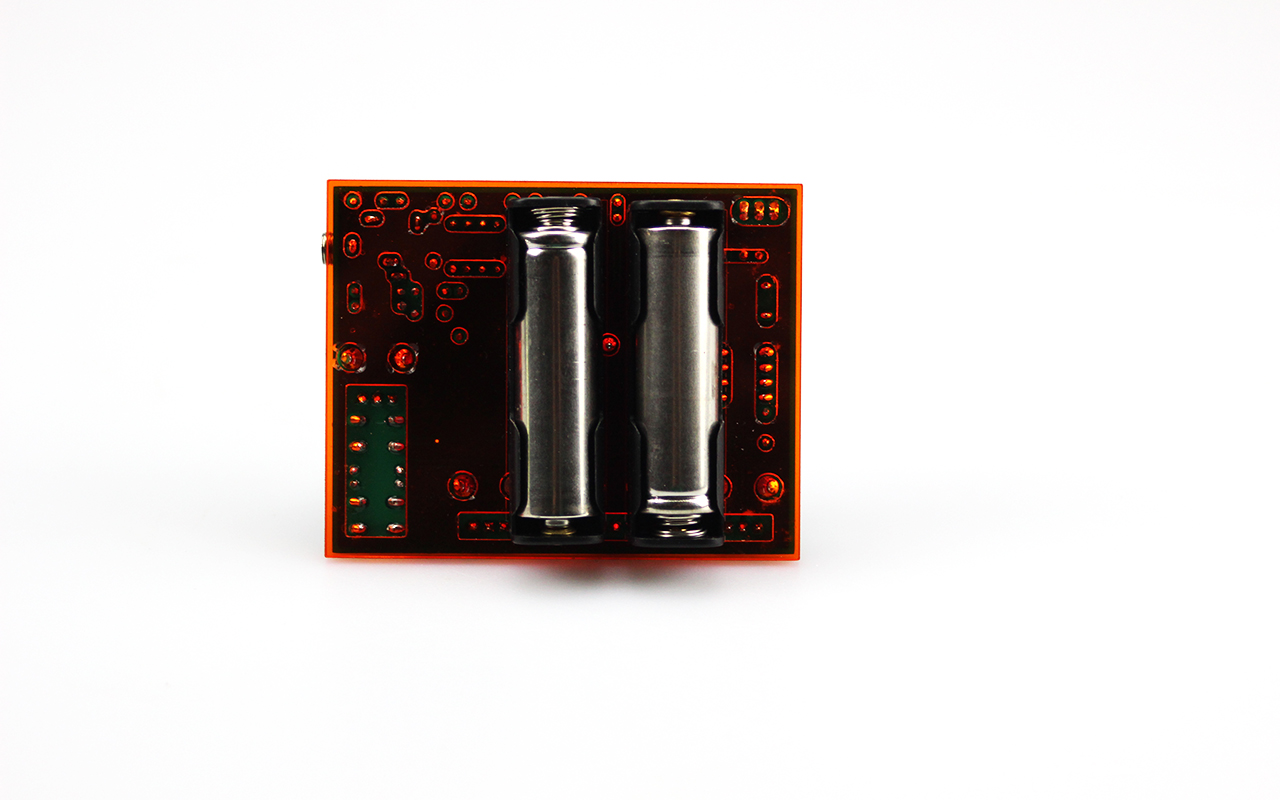
The goof series is a collection of sythesizers I‘ve built during the past years for my dad who is a huge synth enthusiast. All of the goofs (beside the first one) are powered by two AA batteries and have a 3.5 mm audio jack for output.
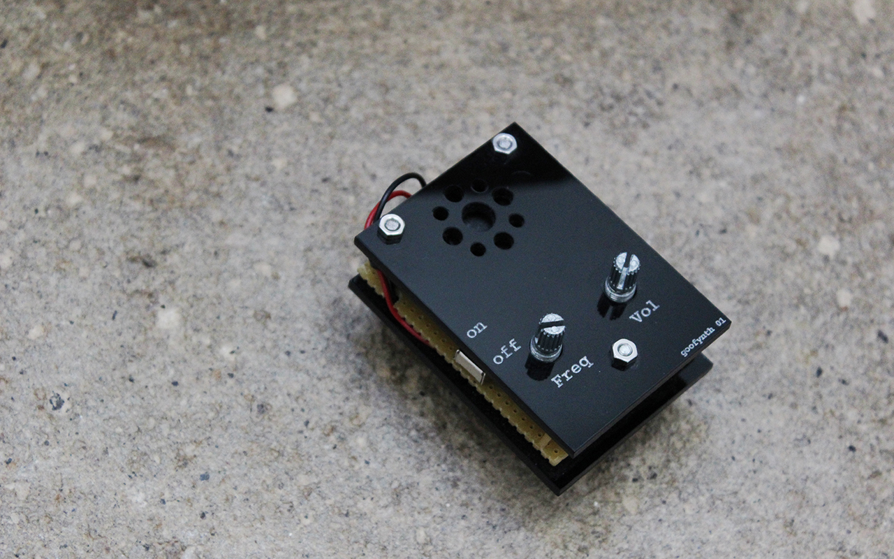
goofynth 01
The first one! A very simple squarewave synth based on a 555 Timer and powered by a 9V battery.
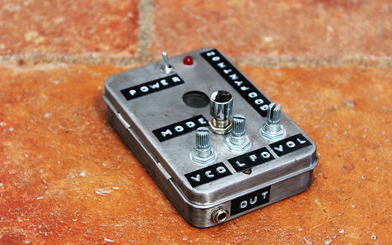
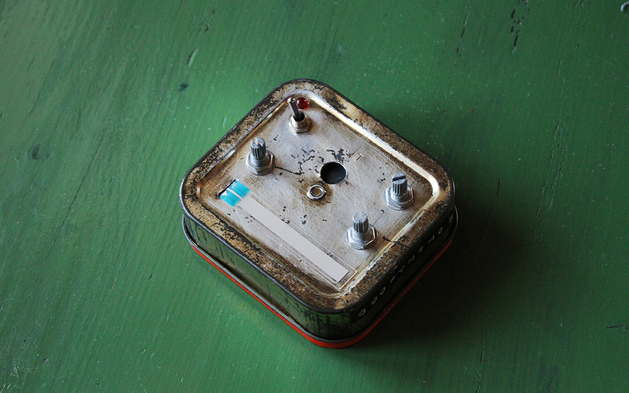
goofynth 02
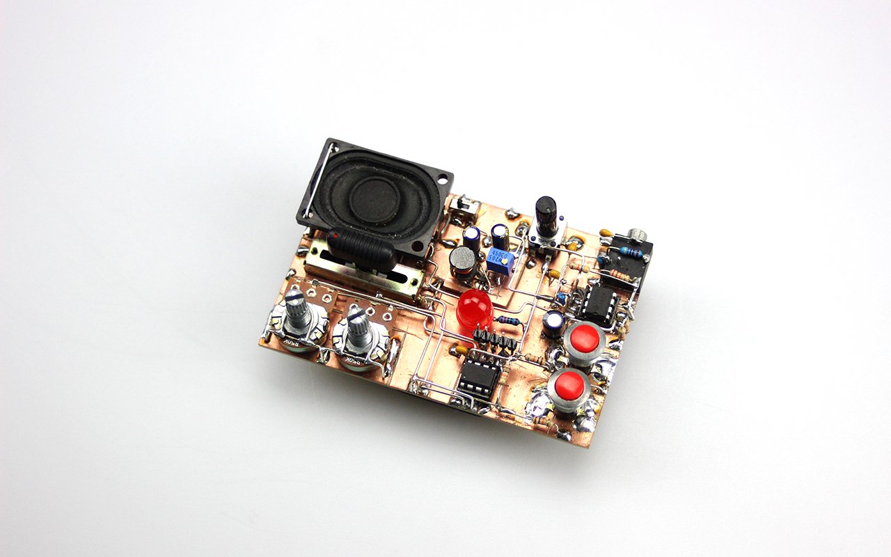
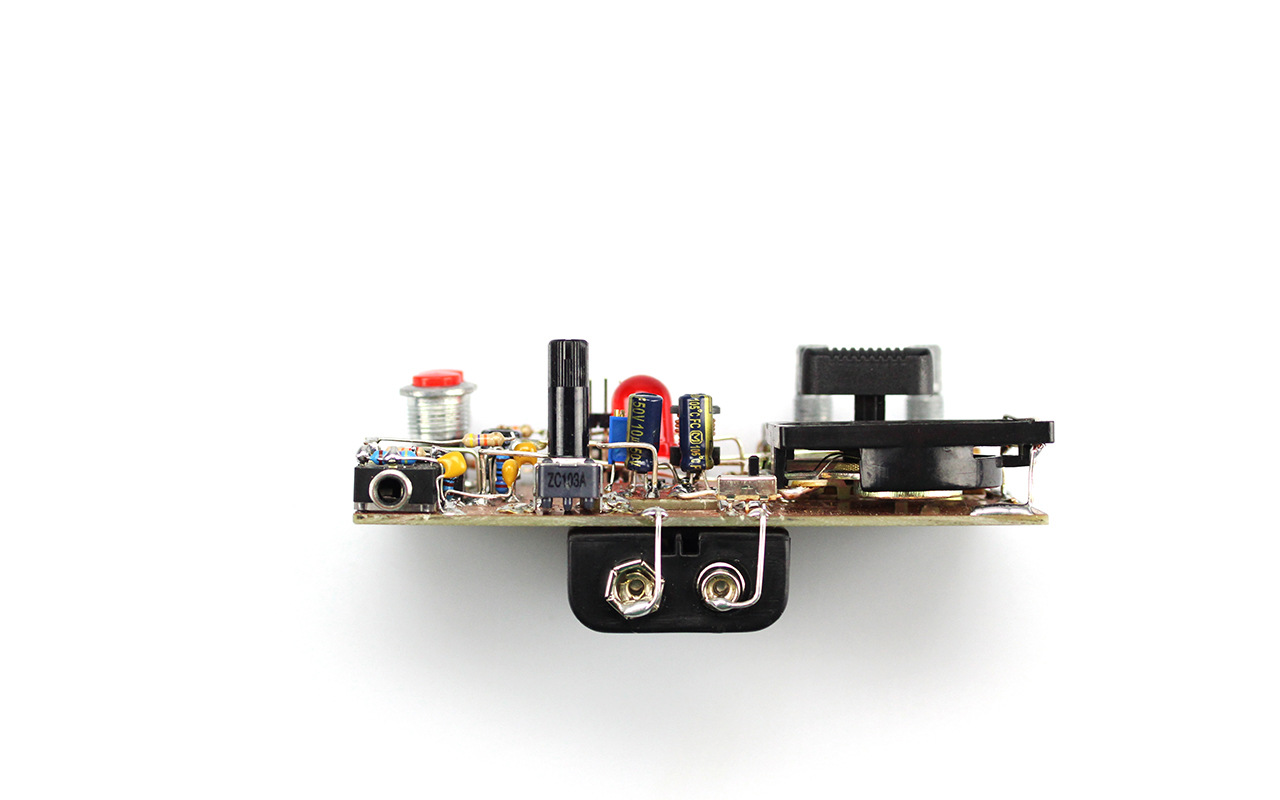
This one is an AM-synth based on an ATtiny45. I tried to implement the synthesis algorithm but something went a bit wrong so now it produces very sharp but charming noisy sounds. LFO, VCO and volume can be controlled and there is also a button for changing the waveform and switching between different modes.
goofynth 03
The 03 is a FM-Synth based on an ATmega328. It has a ribbon controller for the VCO and also a lowpassfilter.
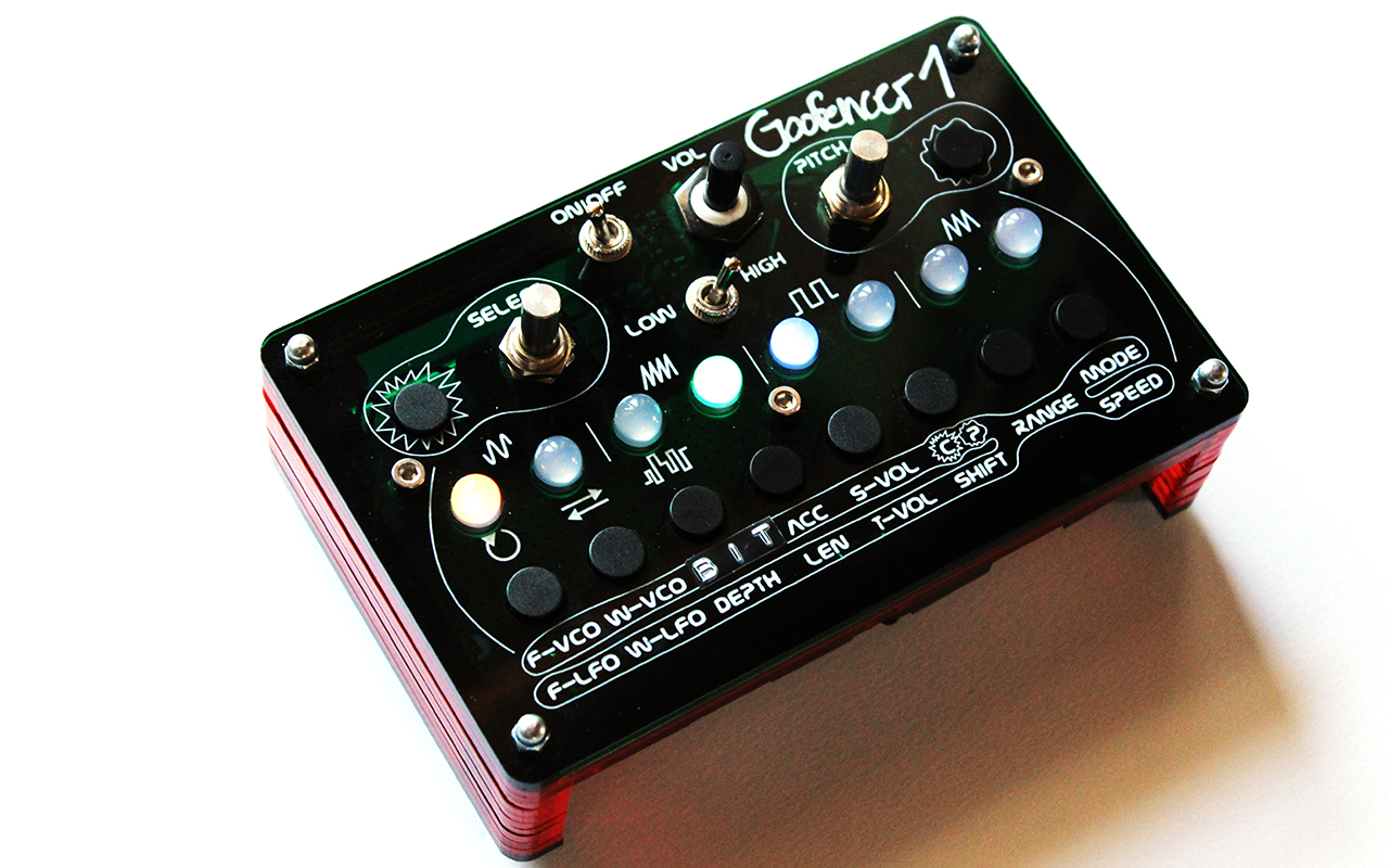
goofencer 01
This is the first sequencer in the series. It has eight steps and two tracks. The interface consists of many buttons, eight RGB leds and two very smooth rotary encoders. Basically the sounds are AM-sounds with an envelope and also effects like a bitcrusher can be applied. The length and the pitch of each track can be varied easily and there are some more mechanisms that make it possible to create a little beat and melody on the fly. The idea was that the sequencer serves as backing when playing on the other goofencers.
goofynthXtra 01
Instead of a programmatically copy of analog synths (with different oscillators, filters and effects) the sound is basically produced by an up counting number which is then manipulated with different bit operations. The last eight bits of the result are then used as a audio sample.The micro controller in use only has digital outputs, so basically these outputs can have just two different states, in this case it is 0 volt and 5 volt. That is not enough resolution for representing an audio signal, but luckily there is a technique called pulse code modulation. Therefore a PWM wave is generated, which is a signal that alters between the two states at a very high frequency, in fact several million times per second. Passing the signal through a lowpass filter will eliminate the high frequency portion and a smooth ‚analog‘ signal will be left. By changing the duty cycle of the PWM wave, that means changing the ratio of the on and off time, voltages that lie between 0 and 5 volts can be achieved. With this principle one can produce a huge variety of different sounds and sound patterns, rhythmical and melodious.The first version of it was built-in manhattan style, later on I have also manufactured a PCB.